Voltra Fixed Mount – L Plate
One bent steel plate that attaches a Voltra DIY Dock to your power rack with standard rack hardware.
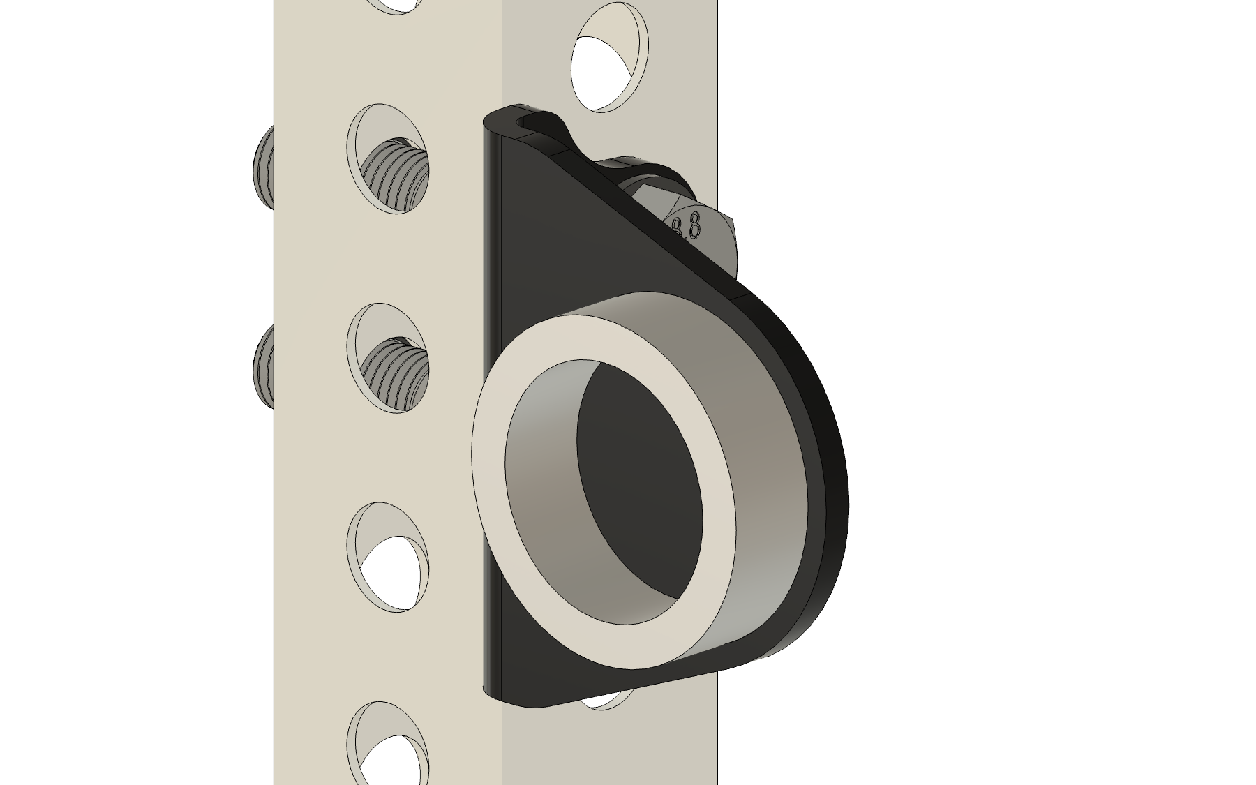
Alternate mounting: attach the dock to the plate before you attach the plate to the tube. The strength calculations are for the standard mounting only.
Black: the plate, your download (121.0 × 142.0 × 77.1 mm). Gray: the rack, dock and hardware, for reference.
Price and file
Plate price · RMFG · powder coated
- 1 plate
- $42.93
- 2 plates
- $31.98 each
- 4 plates
- $27.74 each
- 6 plates
- $26.18 each
- 12 plates
- $23.07 each
Quote from 1 Oct 2026, before tax. Ground shipping from RMFG is free. Get a new quote when you order. Narrow washers, if your rack needs them: $6.80 for two from McMaster (29 Sep 2026).
The plate only, in millimeters. Upload this file to RMFG to order the plate. How to make it
Make it
- Order the plate from RMFG. Upload the STEP file at rmfg.com. Select Steel, Hot Rolled, 0.313 in. Select a powder coat in the color that you want. Do not add tapping or countersinking. The model includes the bend. Order one plate for each mount.
- Get the dock and the rack hardware. Use a Beyond Power DIY Dock with its eight M4 × 16 screws and its magnetic pad. Use two rack bolts, 1 in or M24, with their nuts and washers. The washers under the bolt heads must not be wider than 1.75 in (44.5 mm). REP’s M24 washers fit. Standard 1 in SAE and USS washers are 2 in wide or more, and Rogue’s washers are too wide. If your washers are wider than 1.75 in (44.5 mm), use two McMaster 94744A438 narrow washers for each mount.
Tools: a hex key or torque driver for the dock screws, a ruler, and two full-length wrenches: 36 mm for M24 bolts, or 1-1/2 in for 1 in bolts.
Use it
- Examine the plate. Make sure that the flange is flat and that the bend is at 90°. Measure these two distances:
- From the front face of the dock section to the near edge of each large hole: 39.0 mm.
- From the rear face of the flange to the nearest small hole: 37.5 mm.
If a distance is different by 1 mm or more, make sure that the plate fits your rack.
Measure from the face to the nearest hole edge, as shown. Dimensions are in millimeters. -
Attach the dock to the plate. Do this on a bench. Put all eight M4 screws through the plate from the rear. Do not tighten a screw until all eight screws are in position. Tighten the screws in a cross pattern to 2–2.5 N·m. Put the magnetic pad in the center of the ring. Refer to Beyond Power’s DIY Dock installation instructions.
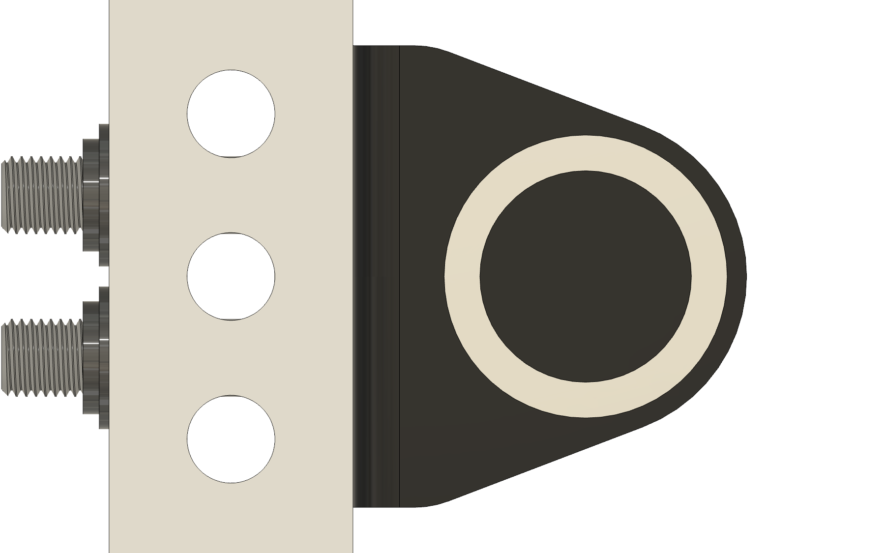
The dock face, from the front. The dock ring is at the center of the round end. -
Attach the flange to the rack. Use two adjacent side holes. Put a washer that is not wider than 1.75 in (44.5 mm) under each bolt head. Put the bolts through the two walls of the tube. Install the far-side washers, split washers and nuts. Do not tighten the nuts.
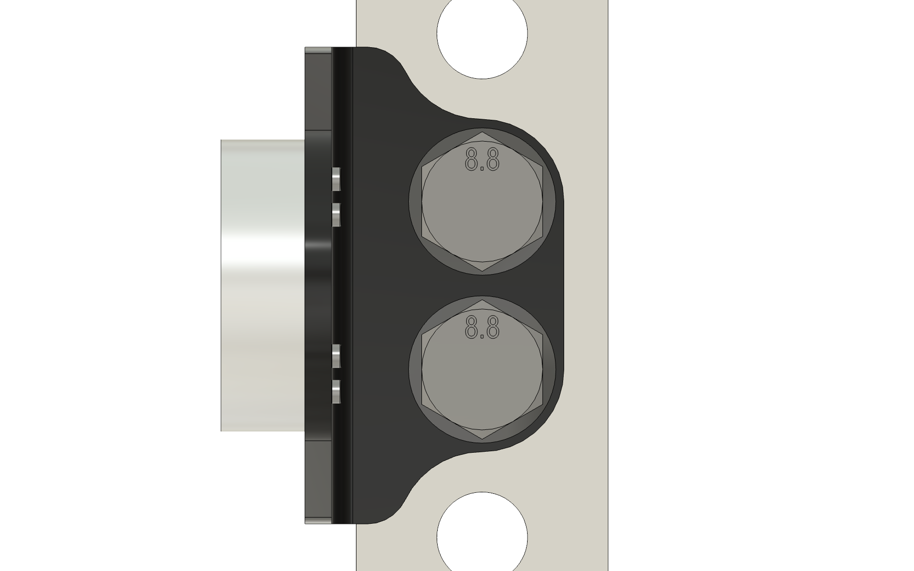
The flange from the rack’s side. Each bolt head has a washer under it. The holes above and below stay free. -
Pull the plate forward, then tighten the nuts. Pull the plate forward until it touches the two bolts. Align the head washers with the bolt heads. Hold each bolt head and tighten its nut firmly with a full-length wrench. Make sure that the flange and the washers are flat on the rack. Make sure that the dock face does not touch the rack.
Installed on a REP upright. The pale ring is the DIY Dock. The nuts behind the upright are not shown.
Alternate mounting: you can also install the plate with the dock section in front of the tube. To see it, select Alternate in the 3D view. Attach the dock to the plate before you attach the plate to the tube. The dock screw heads have 4.5 mm of clearance to the tube. The strength calculations are for the standard mounting only.
To remove: remove the Voltra from the dock. Hold the plate. Hold each bolt head and remove its nut. Then remove the bolts and the plate.
Technical details
Fit
The plate fits 3 × 3 in uprights with 1 in bolts, and 75 mm metric uprights with M24 bolts. It attaches to the side face of the upright with two adjacent side holes, which must be on a 2 in or 50 mm pitch.
- REP PR-5000: 75 mm tube, 27 mm holes at 50 mm pitch, M24 bolts. These dimensions are measured. When the plate is installed, you can use a socket of up to 50 mm diameter in the adjacent holes.
- Rogue Monster 2.0: 3 in tube, 1-1/16 in keyholes at 2 in pitch, 1 in bolts that are 4-3/4 in long. These dimensions are from Rogue’s drawings. Use the narrow head washers.
Dimensions and specifications
- Part
- FM16-1-R6Design FM16, part 1, revision 6
- Revision date
- 1 Oct 2026
- Status
- Not built yet
- Material
- Hot-rolled steel, 5/16 inRMFG’s 0.313 in (7.94 mm) plate. The calculations use A36: minimum yield 248 MPa (36 ksi).
- Finish
- Powder coatAny color. RMFG applies it.
- Size, bent
- 121.0 × 142.0 × 77.1 mmOut from the upright × height × front to rear
- Flat blank
- 184.5 × 142.0 mm
- Mass
- Approximately 1.18 kgSteel at 7.85 g/cm³, without the powder coat
- Bends
- One, 90°6.34 mm inside radius (RMFG tooling)
- Bolt holes
- Two, 27.5 mm50.4 mm apart, for M24 or 1 in bolts
- Dock holes
- Eight, 4.7 mmThe DIY Dock M4 pattern
- Dock position
- 71.5 mm outFrom the side of the upright to the dock center. The base of the dock is 15.3 mm in front of the rack.
- Height
- 142 mm at the bend, 99 mm at the bolts
- Hardware to buy
- None, if your rack’s washers fitWashers wider than 1.75 in (44.5 mm), such as Rogue’s: two narrow 1 in washers, McMaster-Carr 94744A438
- Tolerances
- The fabricator’s standardCut and bend to the STEP file. All holes are clearance holes.
Dimensions in millimeters. The views and dimensions are from the fabrication STEP, and the mass is from the Fusion model. The bend radius is from RMFG’s STEP readback. Positions on the dock face are from the flange face against the upright (0). Dashed gray lines show the REP upright for reference. REF marks a reference dimension.
Load calculations
Yield is the stress at which steel starts to change shape permanently. Minimum yield is A36’s specified lower limit. Expected strength is the higher yield value assumed in these calculations.
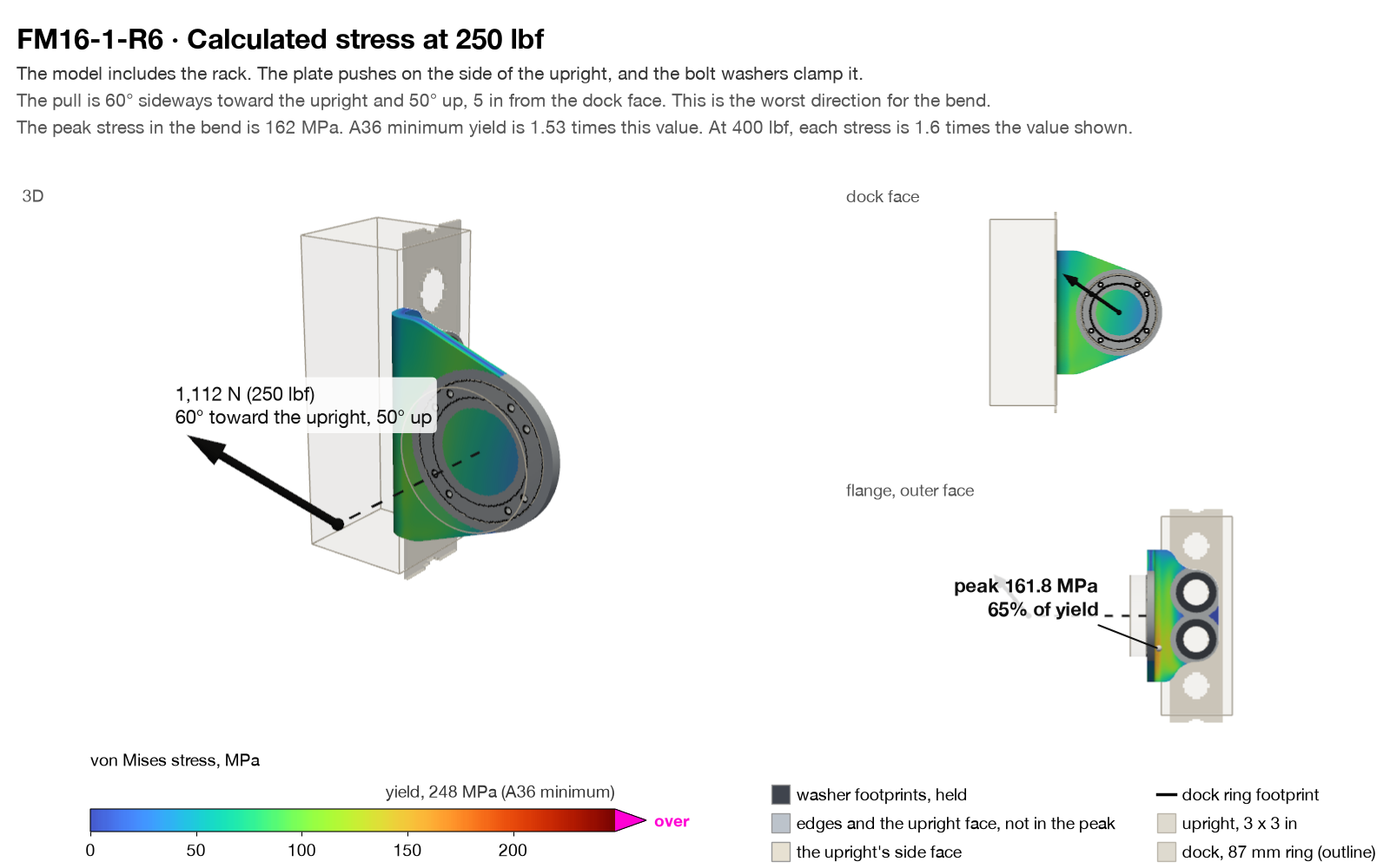
All values in this section are from calculations. 250 lbf is the maximum in the Voltra’s weight modes, with Overdrive. 400 lbf is the maximum in its Isometric Testing mode. At 250 lbf, the stress in the plate is less than the minimum yield of A36 steel. At 400 lbf, the stress at the bend is 259 MPa, 4% more than the 248 MPa minimum yield. With the thinnest permitted stock, it is approximately 11% more.
The model includes a rigid REP upright as a contact, and fixed areas under the bolt washers. The load is 127 mm from the dock face, in 36 directions up to 75° from straight out, horizontally and vertically. RMFG does not specify the steel grade, so the calculations use A36.
| Where | At 250 lbf | At 400 lbf |
|---|---|---|
| The bend, the area with the most stress | 162 MPa (1.53×) | 259 MPa (0.95×) |
| The flange at the edge of the bolt washers | 151 MPa (1.64×) | 241 MPa (1.03×) |
| The remaining area of the flange | less than 146 MPa | less than 233 MPa |
| The dock section | less than 115 MPa | less than 184 MPa |
Nominal 5/16 in plate. The limit is the 248 MPa minimum yield of A36. The ratio in parentheses is the minimum yield divided by the calculated stress. The model uses the properties of flat plate at the bend, so the result is not a limit for the inside face of the bend.
Higher loads and repeated loads
At the expected strength of A36 (1.3 × the minimum yield), a 400 lbf load and unload causes no yield. The permanent dock rotation is 0.001°. The expected strength is an assumption, not a value from a material certificate. These calculations do not include the eccentric setting of Advanced Mode or impact during docking.
The 982 lbf (4,366 N) overload is adapted from a formula in ISO 20957‑2 for equipment with external loads. With expected-strength A36, the plate holds the full load in five directions. The maximum plastic strain is 0.72%. The maximum permanent dock rotation is 0.32°.
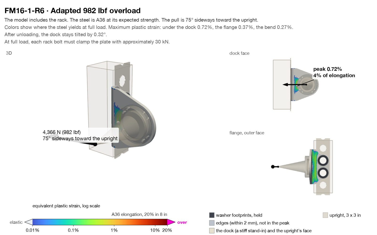
The overload calculation uses a clamp force of approximately 30 kN on each rack bolt. The model does not include the dock screws. An EN 1993-1-9 fatigue calculation gives approximately 140,000 pulls at 250 lbf in the worst direction, and 41,000 pulls at 375 lbf.
Rotation: the friction of the clamp holds approximately 200 N·m during heavy vertical pulls. If the clamp slips, the plate can turn up to 8.4° on REP before the two bolts stop it. When you pull the plate forward before you tighten the nuts, you remove the forward play.
Files and revisions
- FM16-1-R6 · fabrication STEPBent plate, millimeters · 46 KBSHA-256 13b3a8ab43152e713704c338699da0da9d2b4811d6a6bf77b0a68ceaee3aa99e
- FM16-1-R6 · viewer mesh
R6 · 1 Oct 2026 · First shared revision.